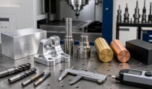
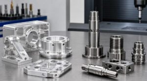
Στροφή CNC is one of the most efficient manufacturing processes for producing round and cylindrical components. Shafts, bushings, pins, spacers, threaded fittings, and many other precision parts can be manufactured quickly and accurately on CNC lathes.
However, a part being round does not automatically mean it is easy or economical to turn. Features such as thin walls, deep internal holes, unnecessarily tight tolerances, and difficult-to-reach grooves can increase machining time, tooling costs, and quality risks.
Design for manufacturability, or DFM, addresses these issues before production begins. By understanding how a turned part will be held, cut, measured, and separated from the raw material, designers can improve quality while reducing lead times and production costs.
This guide explains the most important DFM principles for designing CNC turned parts.
1. Design Around the Turning Process
During CNC turning, the workpiece rotates while a cutting tool removes material. Because of this motion, turning is best suited to parts with rotational symmetry.
Common turning features include:
- Εξωτερικές και εσωτερικές διάμετροι
- Steps and shoulders
- Ταπετσαρίες
- Αύλακες
- Μπόρες
- Chamfers and radii
- External and internal threads
Whenever possible, arrange these features around a common centerline. A design dominated by concentric diameters can usually be produced quickly and accurately in one or two setups.
Side holes, off-center holes, flats, slots, and other non-rotational features may require live tooling, a mill-turn machine, or a separate milling operation. These features are possible, but they increase programming, setup, and inspection requirements.
Before adding one, consider whether it performs a necessary function or whether the same result can be achieved with a rotationally symmetric feature.
2. Control the Length-to-Diameter Ratio
Long, slender parts are more difficult to turn than short, rigid components. Cutting forces can cause a slender workpiece to bend away from the tool, leading to chatter, taper, poor surface finish, and dimensional variation.
As the unsupported length increases relative to the diameter, the risk becomes greater. There is no universal ratio that applies to every component because the result also depends on the material, tolerance, cutting parameters, and available support.
A practical design should:
- Keep unsupported sections as short as possible
- Avoid abrupt transitions into long, thin diameters
- Add larger supporting diameters where the function allows
- Place critical dimensions near stable, well-supported areas
- Avoid specifying very tight straightness or cylindricity without a functional need
Long shafts may require a tailstock, steady rest, follow rest, or multiple operations. Small, slender components may be better suited to Swiss machining, where the material is supported close to the cutting tool.
Discuss long or flexible parts with the manufacturer early. A small geometry change can sometimes eliminate a difficult setup.
3. Avoid Unnecessarily Thin Walls
Thin walls can deform under cutting pressure and clamping force. They may also vibrate during machining and move after material is removed. This makes diameter, roundness, and surface finish more difficult to control.
The acceptable minimum wall thickness depends on the material, diameter, length, and required tolerances. Aluminum generally permits thinner walls than stainless steel because it is easier to machine, but the complete geometry must still be considered.
To improve machinability:
- Use consistent wall thickness wherever possible
- Shorten long thin-walled sections
- Add a thicker rim or supporting shoulder
- Avoid combining thin walls with deep internal cavities
- Apply tight tolerances only to functional surfaces
If a thin wall is essential, the machining sequence becomes especially important. Roughing and finishing passes may need to be separated, and special soft jaws or internal supports may be required.
4. Simplify Deep Holes and Internal Cavities
Internal features are usually more difficult to machine than external ones. A long boring bar has less rigidity, limited chip evacuation, and a greater tendency to vibrate. Deep, small-diameter holes create similar problems.
Whenever possible, reduce the depth-to-diameter ratio of holes and bores. Use standard drill sizes, provide sufficient tool clearance, and avoid deep internal corners that require unusually long tools.
For blind holes, remember that a standard drill leaves a conical bottom. Requiring a perfectly flat bottom may add a secondary operation with an end mill or specialized tool. If the bottom shape has no functional effect, allowing the normal drill point is more economical.
Designers should also clearly distinguish among drilled, bored, and reamed holes:
- Drilling is efficient for creating a hole but offers moderate accuracy.
- Boring improves diameter, alignment, and concentricity.
- Reaming can provide a controlled diameter and improved finish in suitable holes.
The drawing should specify only the accuracy and finish required by the part’s function.
5. Use Practical Radii and Chamfers
CNC turning tools have physical nose radii, so perfectly sharp internal corners are generally impractical. Internal shoulders should include a radius that is compatible with a standard cutting insert.
A larger internal radius can improve tool strength, reduce stress concentration, and allow more efficient machining. However, it must not interfere with mating components. If another part must sit against the shoulder, consider adding a relief groove or a matching chamfer.
Chamfers are useful for:
- Removing sharp edges
- Guiding components during assembly
- Protecting thread starts
- Making shafts easier to insert into holes
- Reducing burrs on exposed edges
Not every edge needs a separately dimensioned chamfer. A general note such as “break sharp edges” may be sufficient for noncritical edges, provided the acceptable edge condition is clear.
6. Design Grooves and Undercuts Carefully
Grooves and undercuts often serve important functions, including O-ring installation, retaining-ring location, thread relief, and tool clearance. Their width and depth should be selected with available tooling in mind.
Very narrow or deep grooves require thin tools with limited rigidity. This may reduce cutting speed and increase the risk of vibration or tool breakage. Standard groove widths are generally more economical than unusual dimensions requiring custom tooling.
For functional grooves, specify the dimensions that affect performance rather than applying tight tolerances to every surface. An O-ring groove, for example, should be based on the requirements of the selected seal and operating conditions.
Thread relief grooves should provide enough room for the threading tool to exit cleanly. Without adequate relief, complete threads near a shoulder may be difficult or impossible to produce.
7. Make Threads Easy to Machine and Inspect
Standard threads are faster to manufacture, easier to inspect, and more compatible with commonly available gauges. Use standard metric or unified thread sizes whenever possible.
Good thread design practices include:
- Providing a chamfer at the thread entrance
- Specifying the thread standard and tolerance class
- Avoiding unnecessarily long threaded sections
- Providing tool runout space near shoulders
- Including adequate depth beyond usable internal threads
- Clearly identifying left-hand threads when required
Blind internal threads need extra depth for the drill point, tap lead, and chip clearance. The full hole depth must therefore be greater than the required usable thread length.
Avoid demanding full threads all the way to the bottom of a blind hole or directly against a shoulder unless it is functionally necessary. Such requirements often need special tooling and may significantly increase cost.
8. Apply Tolerances According to Function
Tight tolerances are among the largest cost drivers in precision turning. They may require slower machining, additional finishing passes, controlled temperatures, specialized inspection equipment, and more frequent process adjustments.
Do not assign the same strict tolerance to every dimension. Instead, identify which features control fit, sealing, movement, alignment, or assembly.
Typical critical features may include:
- Έδρα ρουλεμάν
- Sealing diameters
- Press-fit or slip-fit surfaces
- Νηματοποιημένες διεπαφές
- Mating shoulders
- Concentric diameters
Other dimensions can often use standard machining tolerances.
Geometric tolerancing should also reflect function. Runout, concentricity, cylindricity, perpendicularity, and position requirements can be valuable, but only when they are connected to a clear datum structure and assembly need.
Where possible, machine related concentric features in the same setup. This reduces accumulated positioning error and makes runout requirements easier to achieve.
9. Specify Surface Finish Only Where It Matters
Surface finish should be based on how the surface functions. A seal contact area, bearing seat, or sliding surface may require a finer finish than an ordinary external diameter.
A finer finish usually requires reduced feed rates, additional passes, more careful tool control, or a secondary process such as grinding or polishing. Applying the same fine finish to the entire part adds cost without necessarily improving performance.
Use finish requirements selectively:
- Fine finishes for sealing, sliding, or precision mating surfaces
- Moderate finishes for general machined surfaces
- Cosmetic requirements only where appearance matters
- Unspecified standard finishes for noncritical areas
Surface roughness alone does not define surface performance. Directional tool marks, waviness, and damage during handling may also matter, particularly on sealing surfaces.
10. Select Materials With Machinability in Mind
Material choice affects cutting speed, tool life, chip control, dimensional stability, and surface quality.
Aluminum and brass are generally easy to turn and can support high production rates. Carbon steels vary considerably by grade and heat-treatment condition. Stainless steels may work-harden and generate difficult chips, while engineering plastics may deform from heat or clamping pressure.
The drawing should identify the exact material grade and condition. Specifications such as “stainless steel” or “aluminum” are too broad because different grades can behave very differently during machining and in service.
When several materials satisfy the functional requirements, consider machinability alongside strength, corrosion resistance, temperature resistance, availability, and price. A more machinable grade may reduce total component cost even when its raw material price is slightly higher.
11. Consider Workholding and Parting-Off
A CNC turned part must be held securely while it is machined. Provide enough noncritical surface area for a chuck, collet, or soft jaws to grip the material.
Placing a critical finished surface in the primary clamping area can create marking or distortion risks. Very short gripping lengths may also require custom fixtures or reduced cutting forces.
Parts produced from bar stock are commonly separated with a parting tool. The cut-off face may retain a small witness mark or central nub. If that face requires tight flatness, length, or surface-finish control, a secondary facing operation may be necessary.
Designers should identify whether minor jaw marks or parting marks are acceptable. Clear expectations prevent unnecessary finishing operations and cosmetic disputes.
12. Reduce Setups and Secondary Operations
Every additional setup adds labor, alignment time, and opportunity for error. The most economical turned parts are usually designed so that most critical features can be completed in one setup.
Keep related diameters, shoulders, and bores accessible from the same direction when possible. If the part must be reversed, avoid defining extremely tight relationships between features produced in separate setups unless the function requires them.
Side holes, milled flats, slots, and cross holes may be efficiently produced with live tooling on a suitable turning center. However, their position and complexity still affect cycle time.
A simpler feature does not merely reduce cutting time. It can also reduce programming, fixture design, tool changes, inspection, and handling.
CNC Turned Part DFM Checklist
Before submitting a design for quotation, check the following:
- Is the main geometry rotationally symmetrical?
- Can non-rotational features be simplified or removed?
- Are long, slender sections adequately supported?
- Are thin walls and deep internal cavities minimized?
- Do internal corners have practical radii?
- Are groove widths compatible with standard tools?
- Are holes based on standard sizes where possible?
- Do blind threaded holes include sufficient extra depth?
- Are tight tolerances limited to functional dimensions?
- Are surface-finish requirements applied selectively?
- Is the exact material grade and condition specified?
- Is there enough space for secure workholding?
- Can critical concentric features be machined in one setup?
- Are deburring, heat treatment, coating, and inspection requirements clear?
Συμπέρασμα
Effective CNC turning design begins with the realities of the machining process. Rotationally symmetric geometry, stable proportions, accessible features, standard tools, functional tolerances, and clear drawings all contribute to better parts.
Applying these DFM principles can reduce cycle time, tooling requirements, setup complexity, scrap risk, and inspection costs. It also helps manufacturers provide more reliable quotations and shorter lead times.
For complex or tightly toleranced components, early collaboration with the machining supplier is one of the most valuable design steps. A DFM review before production can identify costly features and suggest practical alternatives without compromising the part’s intended function.
Send Easiahome your 2D drawings and 3D models to receive a manufacturing review and quotation for your CNC turned parts.