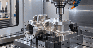
Investment casting creates complex shapes close to their final form. CNC machining then brings selected features to the dimensions and surface conditions needed for assembly. To get consistent results, plan machining allowances, locating datums and inspection together.
Which Features Need CNC Machining?
Investment casting can produce detailed geometries and a good as-cast surface finish, but it may not meet every part’s requirements for size, flatness, hole position or surface finish. Machining is commonly used on features that locate, seal, move or connect with other components.
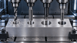
Typical examples include mounting faces, sealing surfaces, bearing seats, precision bores, threaded holes and mating interfaces. These features may need tighter tolerances or smoother surfaces than the casting process can reliably provide.
The first planning step is to distinguish 鋳造面 from machined surfaces. A surface can remain as cast when its finish and dimensional variation do not affect fit or function. A surface should be machined when it must meet a specific size, geometric tolerance or finish requirement.
That distinction affects more than the machining quote. It determines where material must be left on the casting, how the part will be located in a fixture and which features need to be measured at each production stage. If a feature’s function is uncertain, clarify its role before assigning a tight tolerance or machining requirement.
Setting the Machining Allowance
A machining allowance is the material left on a casting so a cutting tool can produce the finished surface. It must be sufficient to clean up the cast surface and achieve the specified geometry. It should not be chosen as a generic amount for every surface or part.
The allowance depends on factors such as the casting’s size and shape, material, process variation, surface condition and machining setup. The location of the surface relative to the casting datums matters too. A part may have enough stock on average but still have too little in one local area if the blank shifts or varies during casting.
Insufficient allowance can leave patches of the original cast surface on a feature that was meant to be fully machined. It can also prevent a bore or face from reaching its required size or finish. Excessive allowance means more material to remove, longer machining time and greater tool use. It can also be a concern when cutting exposes porosity or leaves a wall thinner than intended.
Allowance should be considered surface by surface. For example, a mounting face may need stock on one side, while a bore may need a different allowance strategy to ensure it cleans up around its full circumference. A drawing should make clear which features will be machined and what finished dimensions or tolerances apply. Where general casting tolerances and machining allowance grades are used, ISO 8062-3 provides a framework for specifying them; it does not replace the need to define critical finished features clearly on the drawing. ISO 8062-3:2023
The casting supplier and machining team should review the allowance before production tooling is finalized. They can assess whether the proposed stock is realistic for the geometry and process, and whether the part can be located in a way that leaves enough material on every critical surface. This review is especially useful for complex shapes, thin sections and features positioned far from stable locating surfaces.
Choosing Datums for Cast and Machined Conditions
Datums provide the reference frame for locating, machining and inspecting a part. A datum scheme that works on a finished part may not be usable on the raw casting, which may have uneven or curved surfaces. The drawing therefore needs to show how the team will move from the casting’s condition to the finished part’s reference surfaces.
Start with the datums that represent how the part functions in assembly. Identify which face or feature controls seating, alignment or rotation. Then decide how the casting can be located repeatably before those finished datums exist. Depending on the design, this may involve cast datum targets, temporary locating pads or surfaces that will be machined in an early operation.
A practical sequence is to locate the raw casting using agreed targets, machine an initial reference face or feature, then use that newly machined reference to locate later operations. The specific arrangement depends on the part and fixture. The key is to establish a consistent relationship between the raw casting, the machining setup and the final drawing datums.
Datum targets should be placed where they can be found and used reliably. Avoid locating them on gates, flash, parting lines or areas likely to be removed during finishing. If a target must be cast into the part, make sure its position and form are clear to the foundry and the machinist. It should not disappear during fettling or interfere with the finished geometry.
The VDG P690 guidance calls for datum planes and locating points to be defined systematically so casting inspection and subsequent machining can be coordinated. It also emphasizes agreement between the designer and foundry on those references. VDG P690 guidance A drawing or setup sketch can help explain how the cast targets relate to the finished datum reference frame.
Planning the Machining Sequence and Workholding
The machining sequence should create stable references early and carry them through the remaining operations. If each setup locates the casting from a different rough surface, small shifts can accumulate and affect the relationship between holes, faces and bores.
Workholding needs to support the part without distorting it. Thin walls and irregular sections may move under clamping force, so the fixture should support the casting near the areas being machined. At the same time, it must leave room for tools to reach the required surfaces and for chips to clear.
Consider where stock is concentrated, how the part will be held during each operation and whether the first machined feature can serve as a reliable reference for later setups. If the casting requires several operations, the machining team should review the sequence alongside the datum plan rather than treating the fixture as a late production detail.
It is also useful to review clamping and tool access while the casting design is still being developed. A small locating pad or a modest change in feature placement may make the part easier to fixture and machine. Any such change should be checked against the part’s function and drawing requirements.
Inspecting the Casting and the Finished Part
Inspection should match the manufacturing stages. A casting inspection checks the blank’s condition and relevant cast dimensions. A machining inspection checks the finished features against the part drawing. The inspection plan should state which dimensions apply to which stage so that a rough casting is not judged against a finished-part requirement.
For the casting, measurements can help establish whether the blank has enough material in areas that will be machined. For the finished part, inspection should use the same datum reference frame as the drawing and machining plan. That makes it possible to check whether functional features are in the correct relationship to one another, not just whether each size falls within its individual limit.
A coordinate measuring machine (CMM) is useful for checking feature locations and geometric relationships. A 3D scan may help compare complex cast surfaces or assess the distribution of stock on a blank. These methods can complement each other, but the chosen method should suit the tolerance and feature being checked. A scan alone may not provide the required evidence for a tight bore tolerance or a specific geometric callout.
The inspection plan can identify the critical features to measure, such as bore size and position, mounting-face flatness, hole patterns, runout, thread condition or surface finish. It should also say when checks are required—for example, at first article, during production or at final inspection—and what records the customer needs. A first-article review can confirm that the casting, setup, finished dimensions and inspection approach work together before regular production proceeds.
Dimensional inspection does not establish internal soundness. If porosity or another internal condition is a concern, define the required acceptance criteria and any applicable testing separately. X-ray or other non-destructive testing may be appropriate for some parts, but it should be specified according to the part’s requirements rather than assumed for every casting.
よくある問題とその予防方法
Several recurring problems can usually be traced to gaps between the casting, machining and inspection plans:
| 問題 | 典型的な効果 | 安全防災 |
|---|---|---|
| Too little or uneven stock | A surface does not clean up fully after machining. | Review stock placement against the casting geometry and locating scheme. |
| Too much stock | Longer cycle times and unnecessary material removal. | Set allowances for the specific surfaces and process. |
| Unstable raw-casting location | Machined features shift relative to the part. | Define repeatable locating targets and use them consistently. |
| Different references between operations | Errors accumulate across setups. | Plan how the first machined datum will carry through later operations. |
| Unclear inspection stage or datum | Results are difficult to interpret or compare. | State the part condition and datum reference for each inspection. |
| Internal defects found after cutting | A machined feature may not meet acceptance requirements. | Agree on defect criteria and any required testing before production. |
Resolving these points before production helps avoid late drawing changes, fixture rework and disagreements about whether a part meets the agreed requirements.
What to Include in a Drawing or RFQ
A useful drawing or RFQ package should identify the material, casting process and finished-part requirements. Mark which surfaces remain as cast and which require machining. Show the finished dimensions, tolerances, datum reference frame and surface-finish requirements for critical features.
Where the blank’s geometry affects fixturing or cleanup, include datum targets or a setup sketch. State the required inspection documents and any special testing or acceptance criteria. If the part will be evaluated against a general casting tolerance or machining allowance standard, name the standard and make clear which requirements apply.
Providing a 3D model alongside a dimensioned drawing can help the casting and machining teams review complex geometry. It does not remove the need to identify the controlling dimensions and tolerances. Critical requirements should be explicit and agreed before production begins.
Build One Plan from Casting to Inspection
A machined investment casting is easier to produce consistently when the allowance, locating strategy, machining sequence and inspection method are planned as one process. Clear drawings and early review help the foundry, machinist and customer align on how the part will be made and measured. For a new part, a drawing and model review can identify key machining and inspection questions before production tooling is committed.
よくある質問
Q: Can investment cast parts be CNC machined?
A:Yes. CNC machining is commonly used to produce precise features such as mounting faces, bores, threads, bearing seats and sealing surfaces.
Q: How much machining allowance should an investment casting have?
A:There is no universal allowance. It depends on the material, part geometry, casting variation and machining setup. Allowance should be specified for each surface that requires machining and reviewed with the supplier.
Q: How do you choose datums for machining an investment casting?
A:Start with the finished part’s functional datums. Then define stable locating points for the raw casting and establish machined reference surfaces that can be reused in later operations.
Q: How are machined investment cast parts inspected?
A:Inspect finished dimensions and geometric tolerances against the drawing’s datum reference frame. A CMM can measure feature size and position; scanning may help assess complex cast surfaces or stock distribution.
Q: What should an RFQ include for a machined investment casting?
A:Include the part drawing and 3D model, material, machined surfaces, finished tolerances, datum scheme, surface-finish requirements and any inspection or testing requirements.