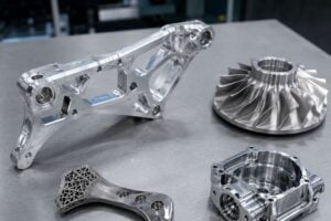
In mechanical manufacturing, the boundary between what a designer can imagine in CAD and what a machinist can physically produce is constantly shifting. However, there is a fundamental law in manufacturing: Complexity equals Cost.
When a design ignores the physical realities of the shop floor, it leads to “unmachinable” parts, excessive tool breakage, and skyrocketing lead times.
This guide explores why certain structures increase CNC machining difficulty and how you can optimize your designs to ensure quality without breaking the bank.
Why CAD Doesn’t Always Translate to CAM
Designers often work in a “perfect” digital environment. In CAD, a 90-degree internal corner is just a click away. In the real world, CNC machining relies on rotating cylindrical tools. A round tool cannot, by definition, cut a perfectly square internal corner.
This is the Complexity-Cost Paradox. As a part’s geometry becomes more intricate, the manufacturing process requires specialized tooling, more complex programming (CAM), additional setups, and slower feed rates. If these factors aren’t managed through DFM, the scrap rate rises, and the “cool” design becomes a financial liability.
Top 3 Engineering Hurdles: The “Physical Limits” of CNC
To optimize a design, we must first understand the three most common geometric “pain points” that frustrate CNC operators and drive up quotes.
1. Deep, Narrow Grooves and High Aspect Ratios
One of the most frequent challenges in CNC machining involves deep pockets or narrow grooves, often found in heat sinks or valve bodies.
- The Technical Root: The physics of tool deflection. A CNC cutting tool acts like a cantilever beam. The longer it is relative to its diameter (the L:D ratio), the more it will flex under cutting pressure.
- The Problem: When a tool “walks” or deflects, it causes dimensional inaccuracies, poor surface finish (chatter marks), and, eventually, tool breakage. Furthermore, in deep grooves, chips (swarf) have nowhere to go. If a tool recuts its own chips, it generates heat and snaps.
- The Solution:
The 4:1 Rule: Try to keep the pocket depth to tool diameter ratio under 4:1.
Tapered Walls: Adding even a 1° or 2° draft angle allows for a tapered tool, which is significantly more rigid than a straight one.
Stepped Designs: If a deep groove is necessary, design it in “steps” so a thicker, more rigid tool can clear the top portion before a slender tool finishes the bottom.
2. Internal Radii and Dead Corners
As mentioned, CNC tools are round. This means every internal corner will have a radius.
The Technical Root: Standard end mills are circular. To get a tight corner, you need a tiny tool.
The Problem:Tiny tools require extremely slow feed rates and are prone to breaking. If the design demands a “sharp” internal corner, the shop must move the part to an EDM (Electrical Discharge Machining) machine. EDM is precise but incredibly slow and expensive.
The Solution:
Over-Sizing: Always make your design’s internal radius at least 10% larger than the tool radius you expect to use. This allows the tool to move through the corner without “burying” itself, which reduces vibration.
Dog Bone Fillets:In assembly parts where a square component must fit into a pocket, use “dog-bone” or “T-bone” reliefs. These move the radius outside the square footprint, allowing the mating part to fit perfectly.
3. Thin-Walled Geometries
Weight reduction is critical in aerospace and EV sectors, leading designers to push the limits of wall thickness.
The Technical Root: Lack of structural mass.
The Problem: When a wall becomes too thin (typically under 0.8MM for aluminum), the force of the cutting tool causes the material to vibrate or “ring.”
This creates a wavy surface finish and makes it nearly impossible to hold tight tolerances. In extreme cases, the wall can even buckle or tear.
The Solution:
Sacrificial Ribs: Design temporary support ribs that keep the wall rigid during machining, which can be removed in the final pass.
High-Speed Machining (HSM): Using low radial engagement and high spindle speeds can reduce the cutting force exerted on the wall.

Materials & Tolerances
The Material Factor
A “simple” shape in a difficult material is often harder to machine than a “complex” shape in an easy material.
- Aluminum 6061: Highly machinable. You can push the limits of complexity here.
- Titanium Grade 5: Extremely “gummy” and poor at conducting heat. A deep groove in Titanium is 5 X more difficult than in Aluminum.
- Inconel / Stainless 316: Work-hardens quickly. Complex features in these materials require specialized ceramic tooling and constant monitoring.
The Tolerance Trap
There is a non-linear relationship between tolerance and cost.
A part with a ±0.1mm tolerance is standard.
A part with a ±0.005mm tolerance requires a temperature-controlled environment, high-end tooling, and a much slower machining cycle.Optimization Tip: Only apply tight tolerances to critical mating surfaces. For non-functional “aesthetic” areas, loosen the tolerance to save on inspection and scrap costs.
Advanced Solutions for Extreme Complexity
When a design simply must be complex, modern technology offers ways to mitigate the difficulty.
- From 3-Axis to 5-Axis Machining
In traditional 3-axis machining, the tool enters from the top. If you have an “undercut” (a feature hidden from the top view), you have to stop the machine, flip the part, and recalibrate. This introduces Setup Error.
5-Axis CNC allows the part or the tool head to rotate simultaneously. This enables the tool to reach “impossible” angles, reducing the number of setups and allowing for shorter, more rigid tools in deep cavities.
- Hybrid Manufacturing: The Best of Both Worlds
For internal geometries that are physically impossible to machine (like curved internal cooling channels), Hybrid Manufacturing is the answer. We use DMLS (Direct Metal Laser Sintering) to 3D print the complex internal core and then use CNC machining to finish the critical external surfaces to high precision.
Case Study: Optimization of an EV Heat Sink Housing
To illustrate these points, let’s look at a real-world project: an ADC12 Aluminum Heat Sink for an electric truck’s powertrain.
The Original Design (The Nightmare)
Fins: 25mm tall, only 1.2mm thick.
Grooves: 28mm deep with a 3.2mm width (Aspect ratio nearly 9:1).
Corners: R0.5mm at the bottom of a 28mm deep cavity.
Manufacturing Result: High tool breakage, required secondary EDM for corners, total cycle time of 6.5 hours per part.
The Optimized Design (The Dream)
Stepped Fin Design: The grooves were widened at the top to 6.2mm and kept at 3.2mm only at the bottom. This allowed a large, rigid tool to remove 60% of the material quickly.
Radii Adjustment: The bottom R0.5 was increased to R1.55. This allowed a standard 3mm end mill to finish the corner, eliminating the EDM process entirely.
Wall Thickening: Fins were increased to 2.0mm, stabilizing the cut and improving surface finish (Ra improved from 3.2 to 0.8).
The Data Comparison
Item | Before Optimization | After Optimization | Improvement |
Machining Time | 6.5 Hours | 3.2 Hours | 51% Reduction |
Tool Consumption | 10 Tools/Part | 5 Tools/Part | 50% Reduction |
Secondary Processes | EDM Required | Zero EDM | Saved 2.5 Hours |
Scrap Rate | 12% | <1% | Massive ROI |
Conclusion
The Path to Efficient ManufacturingMastering CNC complexity isn’t about avoiding difficult designs.It is about making difficult designs smart.
By acknowledging the physical constraints of tool deflection, vibration, and accessibility, you can create parts that are lighter, stronger, and significantly cheaper to produce.Successful manufacturing is a dialogue.
At the earliest stages of your project, engage with your CNC partner for a DFM audit. Often, a change as small as $0.5mm$ in a corner radius can save thousands of dollars in production costs.Ready to optimize your next project? Upload your CAD files for a comprehensive complexity analysis and see how DFM can transform your production cycle
Frequently Asked Questions (FAQ)
Q: Can CNC machine a perfect 90-degree internal corner?
A: No. All rotating tools leave a radius. If you need a square corner, you must use EDM, a broaching tool, or design a “dog-bone” relief.
Q: Does 5-axis machining make complexity “free”?
A: No. While 5-axis reduces setups, the hourly rate for a 5-axis machine is often 2–3 times higher than a 3-axis machine. The goal is to balance setup savings against machine cost.
Q: How does surface finish (Ra) affect difficulty?
A: Achieving a mirror-like finish (Ra < 0.4) on a complex surface requires “feathering” passes with a ball-end mill. This can double or triple the machining time.