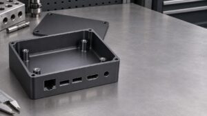
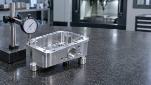
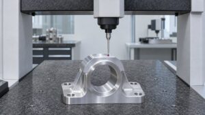
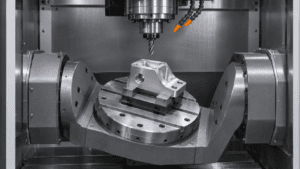
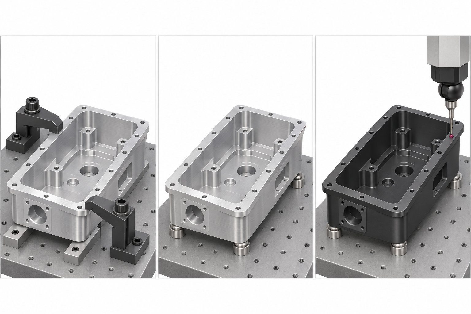
A machined aluminum housing can probe flat on the CNC fixture, lift at one corner when the clamps come off, and return from finishing with a different bore size. Each result describes a different condition of the part. The first comparison can reveal springback. The second needs separate checks for changes in shape and coating buildup.
Aluminum machining deformation is easiest to diagnose when you follow the same part from the fixture to free-state inspection and then through finishing. Record when a change first appears, how the part was supported, and whether the material temperature had stabilized. Those details help the shop decide whether to change the stock, the workholding, the machining sequence, or the finishing allowance.
What changes after the last cut?
When the clamps are released
Clamps can pull a slightly bowed blank against a fixture, and the cutter can produce a flat surface while the blank is held there. When the force is removed, the part springs back. At the same time, removing metal has changed the balance of residual stresses in the remaining section. The free part can bend or twist as it reaches a new equilibrium. Both effects can appear at release. To isolate clamp-induced movement, compare readings with the clamp engaged and released on the same supports, at similar temperatures, with no machining between the checks.
After cooling or a hold
A measurement taken straight off the machine can include thermal expansion. A part with a warmer face or a thicker, slower-cooling region can also change shape as its temperature evens out. Log the part temperature, the measurement time, and the support orientation. A reading after thermal equilibrium establishes a better baseline for comparing later changes. If a repeat reading still moves after temperatures have stabilized, review how the part was supported and handled and compare the change against measurement repeatability before assigning a cause.
After a finishing operation
A thermal cycle can redistribute stress, alter the material condition, or leave a different shape after cooling. The effect depends on the alloy, starting temper, cycle, and constraint. Anodizing can also change the measured size of a feature through oxide growth and pretreatment, even if the underlying part has no measurable change in flatness. A tighter bore and a twisted flange require different investigations. Check the diameter and the form independently, using the delivered condition called out on the drawing.
Why the same program can produce different results
Material and stock history
Record the alloy, temper, product form, stock thickness, lot, and orientation. Rolled plate, extrusion, and forgings have different processing histories. Quenching can leave stresses through the thickness, while stretching can reduce them. A stress-relieved temper such as T651 still has residual stress. A deep pocket near one face of a plate exposes a different stress distribution than a pocket centered through the thickness. Compare blanks from the same lot and record their position and rolling direction when trial parts behave differently. Confirm any change in stock or temper against the drawing and the required mechanical properties.
Structure and stiffness
A housing with a deep off-center pocket, a heavy boss at one end, and a long sealing flange can bow or twist even when no single wall is exceptionally thin. As the pocket opens, the remaining section resists bending differently along its length and width. Critical features on opposite ends may move relative to one another. Mark the spans and surfaces that control assembly, such as a gasket face and the opposing mounting pads. Where design permits, consider balancing the section, shortening a free span, or retaining temporary stock until the main roughing cuts are complete. For cutting-stage deflection and chatter, see the thin-walled CNC machining guide.
Workholding and the order of operations
Place clamps over solid support points where practical, use a documented tightening sequence, and choose a load that securely holds the part without forcing it to conform to the fixture. Check for rocking, debris, and unsupported spans before tightening. If the part moves when a clamp is released, compare clamp positions and support contacts before changing cutter offsets. Dorlin and Karaouni used a heat-treated 7050 demonstrator to study how material removal and changing clamping conditions affect measured post-machining distortion. Published 7050 milling study.
Keep the diagnostic and acceptance readings separate. For example, an indicator at a marked corner can show the direction of movement when clamp pressure is released. A surface scan or an agreed point pattern can then evaluate the entire flange against its flatness requirement. A corner reading alone gives no information about a low spot elsewhere on the sealing surface. If the indicated movement is small, reseat the part and repeat the check before changing the process.
On a high-risk part, rough the main features and leave enough stock for a finishing cut after the shape has been checked. Where geometry allows, distribute stock removal across opposing faces or across stages to avoid removing most of one stressed layer in a single setup. Release the part, let its temperature settle, and inspect the features that will become the finishing datums. Then locate the part on supports that accommodate its free shape, re-establish the datums, and finish the critical features. Use the trial readings to choose the allowance and timing. A fixed overnight hold cannot establish stability by itself.
Published measurements after release and thermal processing
EN AW-2024 after unclamping and a two-week hold
Kuczmaszewski, Pieśko, and Zawada-Michałowska machined 210 × 45 × 10 mm EN AW-2024 specimens with a relieved section and a target floor thickness of 1 mm. They measured deflection after releasing the clamping force and again after two weeks of storage at 22–24 °C. The table gives the reported maximum deflections for the high-speed cutting trials in two rolling orientations. Negative values indicate deflection below the study’s reference plane. Kuczmaszewski et al., 2018, Figures 3c and 4c.
| Rolling direction relative to feed | After machining and release | After two weeks |
|---|---|---|
| Parallel | −0.045 mm | −0.190 mm |
| Perpendicular | −0.142 mm | −0.309 mm |
In these two trials, the magnitude increased by 0.145 mm and 0.167 mm, respectively. The same study found a decrease in magnitude for a different cutting strategy with the rolling direction parallel to feed. These are deflections relative to the researchers’ reference plane. They illustrate why a hold should be followed by a recheck on the actual part and process before it is used as a production control.
7075-T651 after milling, rolling correction, and heating
Lu and colleagues used a coordinate measuring machine to measure 150 mm long T-shaped specimens milled from 7075-T651 plate. They checked the parts after milling, after rolling correction, and after thermal loading. The authors reported post-cycle distortion values of 0.011, 0.002, 0.010, and 0.008 mm for corrected specimens exposed to 120, 160, 230, and 300 °C, respectively. The values apply to that geometry and rolling-correction experiment. For a production part, qualify its own thermal cycle, cooling condition, and post-process geometry. Lu et al., 2023, thermal stability study.
How to record movement on a production trial
Track the same serialized part through the process. For a housing, select a flange flatness result, a pattern or alignment result referenced to the drawing datums, and any bore or thread affected by finishing. Use the same inspection program, point locations, and support orientation for comparable free-state readings. On-machine results can flag a process shift. For drawing acceptance, use the required measurement condition and a suitable, validated method.
- After roughing and release. Record the stock lot, machining stage, support points, and free-state shape. Check that the remaining stock can clean up the datums and functional surfaces.
- After finish machining and thermal equilibration. Record the elapsed time, part temperature, and actual readings. If the job calls for a hold, recheck the same characteristics before sending the part out.
- After the specified treatment. Log the finishing batch, treatment or coating specification, and the elapsed time since return. Recheck shape and size after the part has equilibrated. Apply the drawing’s specified free or restrained condition for final acceptance.
Compare flatness to flatness, and compare bore diameters at the same depths. Keep the actual measurements and the point map where a single maximum value hides the direction of bow or twist. When a bore gets smaller but the flange shape stays within the repeatability of the check, investigate coating growth, masking, and pretreatment first. Agree on any machining allowance with the finisher. When the free-state shape changes, review the treatment cycle and handling together with the machining record. Aluminum Anodizers Council guidance on dimensional change.
If changes begin at a particular thermal step, measure immediately before and after that step under matching stabilized conditions. Where practical, retain a comparable unprocessed witness part from the same stock lot and track it over the same interval. The comparison helps separate the effect of the treatment from changes caused by elapsed time or measurement setup.
What to include in an aluminum machining RFQ
Send the released drawing, CAD model, material and temper, quantities, and finishing specification. Identify the features that control sealing or assembly and state which tolerances apply after finishing. If a part is accepted in an assembly fixture, specify the restraint condition and sequence on the drawing. For a sensitive housing, ask for actual readings before and after the operation most likely to change the part, with enough detail to compare support and temperature conditions.
Send your drawing to Easiahome for review with the critical flange, bore, and datum callouts marked. That gives the supplier a basis for quoting the roughing and finishing sequence, treatment allowances, and the inspection records needed for release.