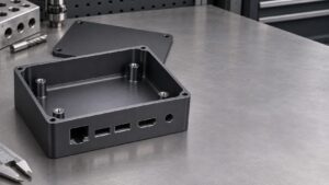
A CNC machined housing can have a bearing bore within size limits, a bolt hole that misses its mating pattern, and a sealing face that is too rough for its gasket. Each result comes from a different check. A bore gauge measures internal size, a coordinate measuring machine (CMM) can check the bolt hole pattern against the drawing datums, and a profilometer measures the texture of the sealing face.
CNC machining inspection starts by matching each drawing callout to a measurement method and a record that shows what was checked. This guide follows one example housing through dimensional, geometric tolerance, and surface roughness checks. The sample report shows how those results inform a release decision.
Start with the drawing and the delivered condition
Use the released drawing revision, the corresponding CAD model where required, and any inspection instructions on the purchase order. Number the characteristics on the drawing so that each report row points to a particular feature or note. On our example housing, the same machined face has separate callouts for flatness across the mounting face and roughness on the annular sealing land. Give those callouts separate numbers because they control different aspects of the surface.
Confirm when each characteristic must be verified. A coated bore may need both a machining check before coating and a final size check after coating if the delivered bore controls fit. Identify masked surfaces and agree on any intermediate measurements used to support final acceptance. Record the condition of the part on the report so a reading taken before finishing can be interpreted correctly.
How to inspect dimensions
Thickness, width, and outside diameter
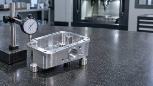
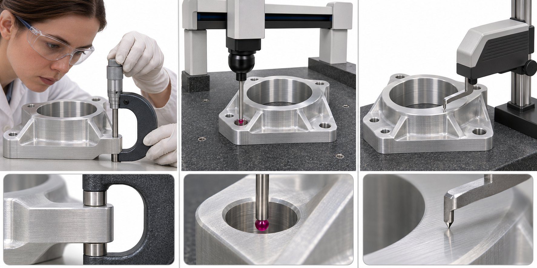
Use a caliper for accessible overall sizes when its accuracy and contact geometry suit the tolerance. For a close thickness or shaft diameter, a calibrated outside micrometer usually offers better control of contact force and alignment. Clean the anvils, avoid chamfers and burrs, and take readings in the locations called out in the plan. On the housing flange, measurements at several locations show whether thickness varies around the part. Flatness of the mounting face requires its own check.
Bearing bores and threaded holes
For the housing’s bearing bore, set a suitable bore gauge against a calibrated ring or other appropriate master. Measure at specified depths and angular orientations where the gauge can seat correctly. The readings show sampled internal sizes and can reveal variation with depth or direction. If the print also controls roundness or cylindricity, use a form measurement strategy with sufficient coverage to evaluate that requirement separately.
For a threaded mounting port, a matching GO and NO-GO thread plug gauge can provide an attribute result under the applicable gauging rules. Record each gauge outcome and identify the thread, for example M6 × 1–6H. A depth gauge or other suitable method can check usable thread depth when the drawing calls it out separately. A plain pin or plug gauge is useful for a quick limit check on a plain hole when that method is agreed. Use a variable gauge when the buyer needs actual values for fit analysis or process monitoring.
Choose the instrument based on the tolerance, range, access, and measurement uncertainty for the task. A display with fine increments can still give misleading readings if the part is warm, the gauge is misaligned, or the fixture distorts the feature. Let the part and gauge stabilize where thermal effects matter and check the setup before recording acceptance data.
How to inspect geometric tolerances
Mounting-face flatness
Flatness limits how far a surface can depart from a plane. For a surface flatness callout, evaluate whether the sampled surface fits between two parallel planes within the specified separation. The callout itself uses no datum reference, even when the controlled face also serves as datum feature A elsewhere on the drawing. Support the housing so the setup does not pull it flat and sample across the functional surface, including areas where milling or release from the fixture may leave distortion.
A CMM with a suitable point pattern or scan can evaluate flatness. A surface plate and indicator can also work when the support, sweep, and evaluation method are suited to the part. Simply subtracting the highest and lowest indicator readings from an arbitrary tilted setup can mix surface form with setup tilt. Agree on how the surface will be sampled when sparse points could miss local deviations.
Bolt hole position, perpendicularity, and profile
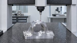
For the housing’s four-hole pattern, the CMM establishes the datum reference frame from mounting face A, long side B, and short side C in the specified order. Probe each hole at enough locations and depths to evaluate the specified axis location, then compare it with the theoretically exact location defined by the basic dimensions. Apply any material condition modifiers specified in the feature control frame. Hole diameter has its own limits, so a hole can meet size and still fall outside its position tolerance zone.
Use the same drawing-led approach for other geometric requirements. A bore perpendicularity check evaluates the bore axis relative to the specified datum. A contoured surface with a profile tolerance needs a probing or scanning path that covers the controlled regions and an alignment that follows the drawing. ASME Y14.5 covers the interpretation of these controls on drawings that invoke it. Renishaw’s scanning overview explains how a scanning probe gathers denser data around features such as bores.
How to inspect surface roughness
For a seal land specified at Ra 0.80 µm maximum, use a suitable profilometer to measure a roughness profile over the defined track. A contact instrument moves a small stylus along the surface and calculates Ra from the filtered profile. Agree on the measurement locations, direction, filter or cutoff settings, and evaluation length under the specified standard or inspection plan. On a face with concentric machining marks, a radial trace crosses the lay. Keep the trace within the sealing land and clear of edges, holes, and grooves unless the plan specifies otherwise.
Check access before committing to a method. A narrow land may lack space for the evaluation length and the extra travel the stylus needs. A deep bore can require a different stylus or a validated alternative. Where a drawing specifies Rz, record Rz under the specified standard. An Ra value alone does not establish an Rz result. An optical method may be suitable where contact access is limited, provided it can deliver the required parameter with a validated setup. Visual inspection can flag scratches or tool marks for separate review.
Repeat measurements at the required locations and report the individual values or governing result according to the agreed acceptance rule. The ISO 21920-2 parameter definitions and ISO 21920-3 specification operators are references for drawings that invoke the ISO profile texture system.
Sample CNC machining inspection report
Illustrative data. Part H-017, drawing Rev B, sample 01 from lot L-014. The housing is inspected after deburring and cleaning in its final, uncoated condition. Drawing dimensions and geometric results are in millimeters. Roughness results are in micrometers. Balloon numbers link the rows to the example drawing callouts.
| Balloon and feature | Drawing requirement | Method | Recorded result | Status |
|---|---|---|---|---|
| 01 · Flange thickness | 12.00 ± 0.05 mm | Outside micrometer, three locations | 12.01, 12.02, 12.01 mm | Pass |
| 02 · Bearing bore size | Ø25.000–25.021 mm | Bore gauge set to a master, two depths and two orientations | 25.008–25.013 mm across four readings | Pass |
| 03 · Mounting-face flatness | 0.040 mm maximum | CMM, distributed face points | 0.026 mm | Pass |
| 04 · Bolt hole diameters | Ø6.60 ± 0.10 mm | CMM, sampled diameters at two depths in each hole | 6.61–6.65 mm across all four holes | Pass |
| 05 · Four-hole position | Ø0.100 mm relative to A | B | C, RFS | CMM, datum alignment and hole-axis evaluation | Ø0.046, Ø0.062, Ø0.071, Ø0.126 mm | Fail |
| 06 · Seal land roughness | Ra 0.80 µm maximum on each trace per example plan | Stylus profilometer, three radial traces | Ra 0.52, 0.59, 0.63 µm | Pass |
Balloon 05 fails because the fourth hole’s reported position error exceeds the diametrical limit by 0.026 mm. All four diameters pass balloon 04. The print calls for position regardless of feature size (RFS) in this example, so there is no bonus tolerance from the hole size. Hold this sample from release, confirm the datum setup and hole identification, and document the nonconformance if confirmed. The result applies to sample 01. The agreed sampling and containment plan determines how to check the rest of the lot.
For balloon 06, the example plan specifies a 0.8 mm cutoff and a 4.0 mm evaluation length, with a separate radial trace at each of three marked locations. Those settings belong to this example. For a real sealing face, use the applicable standard and verify that the available track length suits the agreed method.
A production version of the report should also identify the equipment, calibration status, inspection date, inspector, and sampling scope. Link the CMM detail to the four hole IDs and attach the roughness trace settings where required. If a measured value falls near a limit, apply the agreed decision rule for measurement uncertainty and retain the original reading. For a closer look at datum alignment and traceability in CMM output, see the CMM inspection report review guide.
Specify the inspection evidence with your quote request
Send the current drawing and CAD model, material, finishing requirements, and order quantities. Highlight the features that govern assembly or sealing, and say whether you need first article results, a sampled lot report, or checks on every piece for selected characteristics. Specify where actual readings are required and where a documented gauge outcome is sufficient. That distinction lets the supplier quote the measuring time and reporting scope with the machining work.
Which inspection report should you request?
A first article report documents the characteristics checked on a representative initial part under the agreed scope. A lot inspection report shows which parts and characteristics were sampled for that shipment. A CMM output can support either report for measured geometry. Keep the bore gauge readings, thread gauge outcomes, and profilometer traces tied to the same part or lot records when those methods are used. A purchase order that specifies only a CMM report can leave these other checks undefined.
If a critical feature has restricted access, ask how the supplier will reach it and document the result on the delivered part. Send your drawing to Easiahome for review with the critical callouts marked so the measurement method and inspection deliverables can be discussed before production.