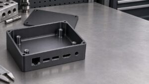
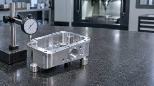
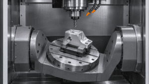
A custom aluminum electronics enclosure has to fit the board, let users reach the connectors, and close without loading the electronics. It also has to look the way the drawing describes after anodizing. A connector opening can meet its width and height tolerances and still miss the installed plug if its position is referenced to a different surface from the PCB mounting bosses.
This guide follows custom aluminum electronics enclosures from the first mechanical layout through CNC machining, trial assembly, anodizing, and final inspection. The focus is a machined body and lid. Use the same functional checks when comparing a billet design with a CNC-machined extrusion and separate end panels.
Choose the machining route from the assembly
Begin with the board envelope, connector drawings, installation direction, and expected production quantity. A pocketed billet body can integrate a cavity, mounting bosses, a lid register, and local features in one piece. It also requires removing much of the starting stock, and a deep cavity or multiple side openings can add cutter reach and setups. If the cross-section can stay constant along the length, an extrusion with machined ends and ports may reduce removal. Include any die cost, minimum purchase, and end-panel assembly in the comparison.
6061-T6 is a common candidate for a machined billet enclosure. If an extruded profile is suitable, review a profile alloy such as 6063 and its specified temper with the manufacturer. Make the material decision with the finish in mind. For a body and lid that must look matched, agree on their alloy and stock condition and approve the appearance on representative material. Compare quotations for the finished kit, including the lid, hardware, machining, masking, inspection, and protective packaging.
Design wall thickness around spans and openings
Define the thinnest remaining section after the pocket, connector rebates, chamfers, and lid features have all been machined. A wall with one large display opening can behave very differently from a wall of the same nominal thickness with small round holes. Check the narrow strips between openings and the material between an opening and the lid fastener or gasket land. Leave material where screw loads or cable insertion forces enter the housing. Where weight matters, remove material in regions with shorter, supported spans first.
Ask the machinist to review pocket depth, internal corner radius, cutter access, and how the part will be supported. A generous corner radius can allow a stiffer cutter. If the PCB corners interfere, check whether board corner clearance, local relief, or a different board insertion direction solves the conflict. Review the floor beneath blind tapped bosses and counterbores as well as the wall itself. A drilled hole needs room for its tip and a tapped hole needs usable engagement beyond the incomplete threads. Mark the required usable thread depth and show any bottom surface that the drill must stay clear of. CNC milling design guidelines.
Locate connector openings from the PCB supports
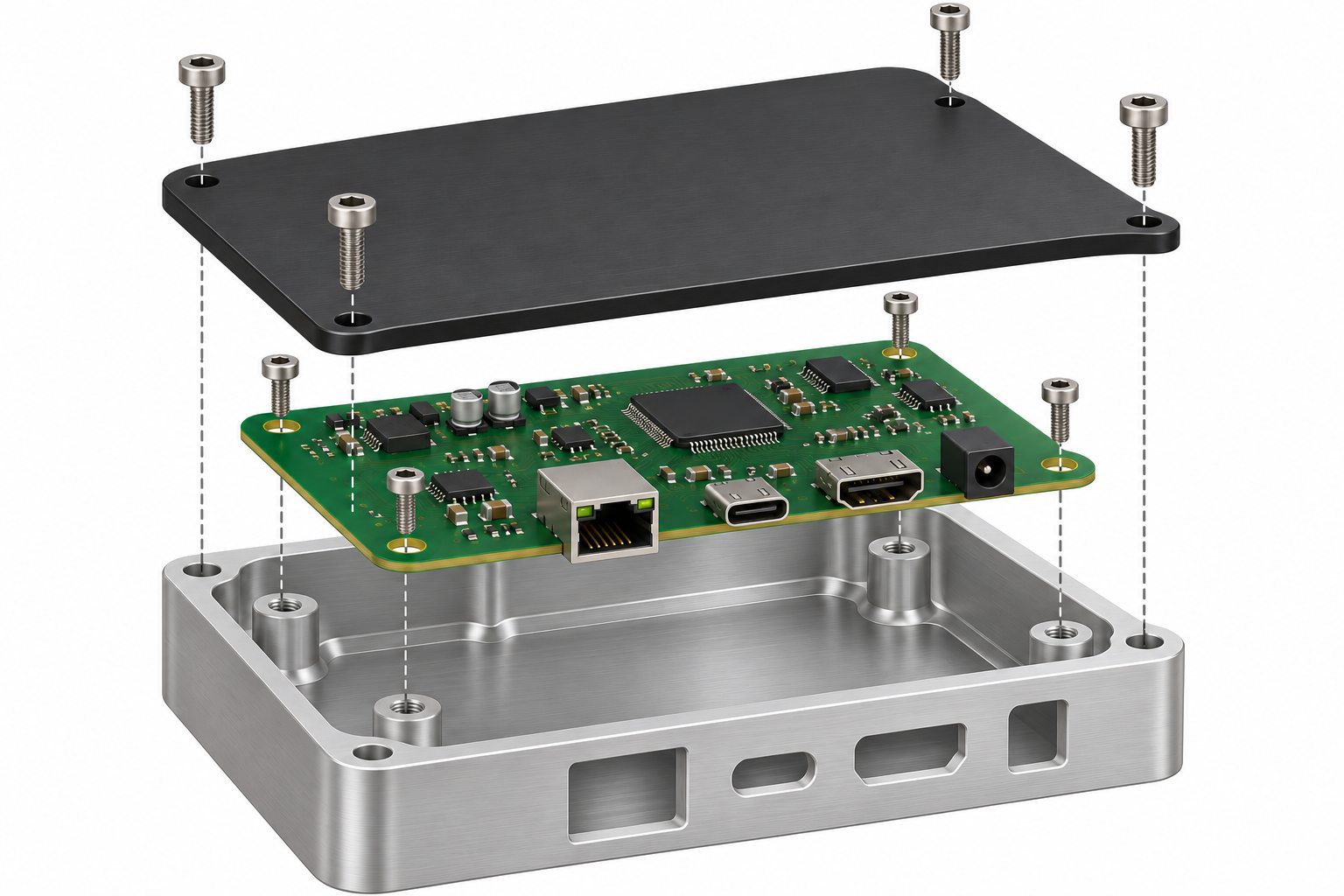
Place the populated PCB in the enclosure model at its assembled height. Use the connector manufacturer’s mechanical drawings and include the housing around the mating plug, latch travel, cable bend, and space for fingers or a tool. This matters with recessed connectors because the plug body can hit the outside wall before the electrical contacts seat. For a panel-mounted connector, check the permitted panel thickness, anti-rotation feature, and room behind the panel for the retaining nut and cable.
Choose a shared set of references for the mounting bosses and the connector openings. A typical layout uses the board seating plane for height and two housing features to locate the board in the other directions. Decide which features locate the PCB and which holes provide fastener clearance. Include variation in the PCB hole pattern, connector location on the board, boss position, and the machined aperture. Set the cutout and its tolerance from the total stack. Enlarging the opening may help plug clearance, but check the visible gap, edge distance, and any gasket or connector sealing requirement.
Plan the lid, hardware, and assembly sequence
Decide what locates the lid before specifying screw clearances. A shallow register or other locating features can control the visible seam while the screws provide clamping force. Check the clearance above the tallest component, the length of every fastener, and the tool access needed to tighten it. An internal boss can be tall enough for the board and still let a screw bottom out before the board is held. If the lid will be removed for service, review the thread and fastener choice for the expected assembly cycles.
Plan how the PCB actually enters the pocket. Some board-edge connectors must pass through their cutouts before the board can drop onto its bosses. Check this motion in CAD and on a trial assembly. Verify that cables can be connected in the intended order and that a harness cannot be pinched under the lid. If a removable panel simplifies insertion, check how that panel locates relative to both the body and the board. A housing, panel, and board can each meet their drawings while their combined tolerances still interfere.
Where the lid seals, define the gasket or O-ring, the mating surface, groove and compression requirements, fastener arrangement, and the test condition. Add any connector, vent, or access cover that is part of the seal to the assembly review. An ingress protection requirement applies to the assembled configuration under the specified test. Agree on the test and installed components with the product team. IEC 60529 IP Code.
Specify anodizing on the enclosure drawing
Put the finish requirements on the drawing before machining is quoted. State the finish type, color, surface preparation, and any specified coating thickness. Mark the primary visible faces and give the shop a physical reference for color and texture when the body and lid must match. Define how they will be viewed, including the lighting and distance when appearance is critical. Specify the direction of a brushed texture or the approved bead-blast appearance where required. Anodized appearance can vary with alloy, stock surface, preparation, and processing. Aluminum Anodizers Council coating guidance.
Mark allowable rack contact locations on a concealed face or another area agreed with the finisher. Define which threads, locating bores, or grounding pads must be masked and state the allowed mask boundary. An anodized surface can interfere with electrical continuity, so identify the contact surfaces and the intended bonding method when grounding or shielding matters. Verify continuity or shielding at the assembly level according to the product requirement. Review where markings go and how their contrast will be accepted after finishing.
Assign the final dimensions to the delivered condition. Oxide growth can narrow a coated bore or opening, and pretreatment can change the size too. On a close-fitting lid register, both mating surfaces may affect clearance. Agree with the machinist and anodizer on the machining allowance or masking approach, then check the finished fit. Put any intermediate machining limits on a clearly identified drawing or inspection plan. Guide to machining tolerances after anodizing.
Inspect fit and appearance on the finished enclosure
Use a trial assembly before finishing to catch design or machining interference. Repeat the checks that are sensitive to coating on the finished first article. Measure the body and lid against their own drawings, then assemble them with the intended PCB, fasteners, connectors, and gasket where applicable. Record the drawing revision, sample ID, finish, and results so the approved configuration is clear to both purchasing and production.
| Feature | What to specify | What to verify |
|---|---|---|
| PCB and ports | Boss height and location, cutout size and position, mating plug clearance | Board seats and the actual plugs insert and latch |
| Lid and hardware | Register, gap or flushness, screw engagement, component clearance | Lid seats and fasteners tighten without bottoming out or loading the PCB |
| Finished appearance | Visible faces, texture, approved sample, rack zones | Body and lid meet the agreed appearance under the specified viewing conditions |
| Critical finished features | Post-coating limits, masking, seal or bonding requirements | Gauge critical fits and run the required assembly checks |
For a production release, agree which features need actual measurements and which require a recorded functional check. Keep the approved finish sample and define how to protect the visible faces during packing. If the lid and body were approved as matching sets, specify how sets should be identified and packed so the delivered parts can be assembled as approved.
Send the files needed for an enclosure quote
Easiahome accepts drawing-based inquiries for custom machined aluminum enclosures. For review, send the STEP models for the body and lid, the revision-controlled drawings, the populated PCB envelope or model, and connector and gasket details where applicable. Include prototype and production quantities, the finish specification, a color or texture reference, and the critical checks you want documented. Identify whether you need the bare machined parts, a finished housing and lid kit, or a defined hardware and assembly scope.
Send your enclosure drawings to Easiahome with the critical ports, PCB supports, and cosmetic faces marked so the machining and finishing requirements can be reviewed together.