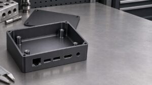
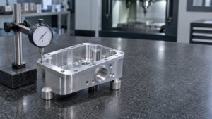
A pocket can look perfectly square in CAD and still be unsuitable for conventional milling. The reason is the cutting tool: a rotating end mill has a circular cutting envelope, so it leaves rounded corners between vertical pocket walls. Choosing the right CNC internal corner radius helps control tool access, cutting stability, machining time and assembly fit.
The best radius is the largest one the component can accept without compromising function. This guide explains the geometry, shows a dimensional comparison and identifies what engineers and buyers should specify before requesting a quotation.
Why CNC Milling Leaves Rounded Internal Corners
Viewed from above, an end mill cuts a circular outline. As it follows two perpendicular walls, its outer edge cannot remove the final material at their theoretical sharp intersection. For a simple vertical corner machined from above, the geometric relationship is:
Part corner radius R ≥ cutter diameter D / 2.
A 6 mm end mill therefore cannot directly produce an R2 mm internal wall corner. A smaller cutter or a different manufacturing approach is necessary. This relationship concerns the cutter diameter, not the small rounding on an end mill’s bottom cutting edge.
External corners are different because the cutter can travel around the outside of the profile. Likewise, a nominally square floor-to-wall junction is a different feature from a vertical pocket corner. Protolabs’ milling guidelines confirm that rounded inside corners are a natural consequence of the process.
Why the Part Radius Should Usually Exceed the Tool Radius
Meeting the geometric minimum does not necessarily produce an efficient cut. When the part radius equals the tool radius, the tool center has no circular travel around that finished corner. Cutting engagement can rise sharply as the tool changes direction.
Harvey Performance’s corner-engagement guidance explains how this condition can contribute to chatter, deflection, tool damage and poor surface finish. A smaller finishing tool, controlled radial engagement and a sweeping path can improve the situation.
For designers, the useful response is to allow more radius where function permits. For machinists, it is to select the tool and path together. A supplier should not enlarge a specified finished radius without approval, even when a larger roughing radius is convenient.
CNC Internal Corner Radius: A 6 mm Cutter Example
For an ideal circular corner, the tool-center path radius equals the part radius minus the cutter radius. The following geometric comparison assumes a 6 mm cutter, with a 3 mm radius. It is not a cutting-parameter recommendation.
| Part radius | Tool-center path radius | Design implication |
|---|---|---|
| R3.0 mm | 0 mm | Geometric limit; corner engagement needs particular attention. |
| R3.2 mm | 0.2 mm | Some circular travel, but little separation between tool and part radii. |
| R4.0 mm | 1.0 mm | More room for a sweeping tool-center path, if the part permits it. |
Sandvik Coromant’s inside-corner finishing guidance recommends a cutter diameter no greater than 1.5 times the component radius. A 6 mm cutter and R4 mm corner meet that relationship. Treat it as application guidance rather than a universal drawing requirement: material, stock, reach and toolpath still matter.
Pocket Depth Can Matter More Than a Small Radius Alone
A small radius becomes more demanding when it sits at the bottom of a deep pocket. The tool must be narrow enough to enter the corner and long enough to reach it, while clearing the surrounding geometry and holder.
Consider an illustrative 18 mm-deep pocket. An R1 mm corner limits the cutter to 2 mm diameter or smaller, giving a pocket-depth-to-diameter ratio of at least 9:1. If function permits R4 mm, a 6 mm cutter becomes geometrically possible, reducing that screening ratio to 3:1. Actual tool overhang may exceed pocket depth, so these ratios do not establish feasibility.
Protolabs Network’s CNC design guide recommends generous vertical radii and short, large-diameter tools where practical. Depth-based rules are useful for initial review, but there is no single minimum radius that suits every material and setup.
A shop may rough the pocket with a larger cutter and use a smaller tool only for remaining corner material. This limits small-tool work, but it still adds operations and may require slower finishing. A tiny radius on one nonfunctional corner can therefore affect the quotation disproportionately.
Material and surrounding geometry also change the decision. A narrow tool reaching into hardened material needs a different review from a short cutter machining an open aluminum pocket. Thin walls may move under cutting forces even when the tool fits. Ask the supplier which feature controls the proposed tool size and whether two drawing-approved radius options would meaningfully change the machining route. Compare complete quotations rather than assuming a fixed saving.
How to Select an Internal Corner Radius
- Start with function. Identify locating faces, seals, moving parts and the full envelope of any mating component.
- Allow the largest practical radius. Review the complete pocket rather than adding a small default fillet to every corner.
- Check depth and access together. Include narrow openings, nearby walls and holder clearance, not just the corner dimension.
- Discuss available tooling. Standard cutter diameters are useful, but the finished part radius does not need to equal a standard cutter radius.
- Consolidate compatible features. Reusing radii can reduce tool changes, provided the material, depth and finish requirements also permit common tooling.
Ask for a manufacturability review before releasing the drawing. A larger radius is only an improvement if it preserves fit, required wall sections and the component’s intended operation.
Remember that increasing an internal fillet leaves more material in the pocket corner. It does not increase clearance for a square insert. Check whether the mating component can accept that reduced corner space before adopting a larger radius. The aim is to balance an efficient toolpath with the actual assembled geometry, not to maximize the radius independently of everything else.
Keep Vertical Corner Radii Separate from Floor Fillets
A vertical internal radius joins two walls in plan view. A floor fillet joins a wall to the pocket bottom in section. These dimensions need separate consideration.
A square-end tool can produce a nominally square floor-to-wall junction, although real tools have finite edge geometry. A specified floor fillet may instead require a suitable corner-radius cutter, a ball-end tool or additional contouring. The floor radius is not automatically half the main cutter diameter.
Show both features clearly when either affects performance. A general instruction to round every edge can create unnecessary work or interfere with seating. Conversely, calling out an unrealistically sharp floor junction can impose requirements that were never intended.
What If a Square Part Must Fit Inside the Pocket?
A square insert can collide with the material remaining at rounded pocket corners. Simply specifying a smaller radius may introduce a difficult machining operation without solving the tolerance problem. Review these alternatives:
- Modify the insert’s vertical corners. Add sufficient rounding or chamfering through the engagement depth. Breaking only its top edge does not remove full-depth interference.
- Add corner relief. Dogbone or T-bone reliefs remove material beyond the theoretical rectangular corner so the mating profile can clear.
- Change the feature or assembly. An open-ended slot or separate component may provide access that a closed pocket lacks.
Fictiv’s machining design guide describes corner-clearance holes for sharp mating parts. Relief geometry still needs approval: check remaining wall section, sealing paths and the required contact area. Evaluate the assembly at its tolerance limits, not just at nominal CAD dimensions.
When a Different Process Is Justified
When a small residual radius is functionally essential, discuss a secondary process such as EDM. Makino describes sinker EDM as suitable for small, deep features in conductive materials that are difficult to mill. Through profiles and blind cavities require different process reviews.
Specify an acceptable residual radius rather than demanding a mathematically perfect corner. Additional setups, electrode preparation and inspection may affect cost and delivery. This is a process-selection discussion, not an assumption that every milling supplier offers EDM.
What to Put on the Drawing and RFQ
Send a matching 3D model and dimensioned drawing, with the material, quantity and required finish. Make the corner requirements explicit:
- Identify the vertical corner radius and any separate floor fillet.
- State the functional radius limits and tolerances that actually matter.
- Show pocket depth, relevant datums and critical mating dimensions.
- Identify permitted reliefs and surfaces that must remain intact.
- Explain whether the corner locates, seals, clears or simply removes weight.
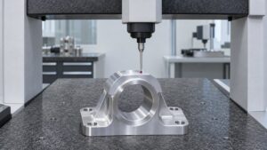
If the corner controls fit, agree on how conformity will be verified. Measuring pocket width alone does not establish the corner profile, and a deburring note does not define its radius. The drawing should make clear whether a nominal radius with a tolerance, an allowed range or another profile requirement governs acceptance. Confirm that the measurement method can access the feature at its specified depth.
Where radius flexibility is acceptable, document the permitted range rather than leaving it to assumption. Easiahome provides CNC machining services. Send your drawing for a corner-radius and machining review, including the mating-part requirements, so tool access and quotation scope can be discussed together.
Frequently Asked Questions
What is the minimum CNC internal corner radius?
For a simple vertical corner cut with an upright end mill, the geometric minimum is the cutter radius. Practical selection also depends on depth, material, access, finish and tolerance. A universal minimum dimension would ignore those conditions.
Will five-axis milling eliminate internal radii?
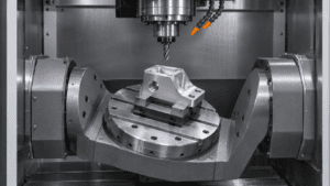
Additional axes improve access, but they do not automatically remove the cutting-tool geometry constraint. Review the actual corner orientation and reachable toolpath before assuming a sharp feature is possible.
Does a larger internal radius always reduce cost?
No. It can permit more stable tooling and simpler paths, but benefits depend on the entire part. A radius that compromises fit, creates extra surface contouring or changes another operation may add work instead.