Design for manufacturability, or DFM, adapts a part so it can be produced reliably at the required quality, volume, cost, and lead time. For CNC machining, it connects function to tool access, workholding, setup strategy, tolerance, finishing, and inspection.
The numerical recommendations in any online guide are starting points. A 0.8 mm aluminum wall may be straightforward when it is short and supported but unstable when it is 80 mm tall. A deep hole may be feasible in one alloy and risky in another. Use the checklist below to prepare a robust design, then review the final geometry with the intended supplier.
Quick CNC DFM Checklist
Before sending a CNC machining RFQ, use this quick DFM checklist to reduce cost, avoid tolerance risk and shorten lead time. The goal is not to make every feature easy at any cost; it is to protect the features that matter while giving the machine shop a clear, repeatable manufacturing route.
DFM item | What to check | Why it matters |
Function and datums | Define critical interfaces, assembly datums and inspection references. | Prevents over-tolerancing low-risk features while leaving important geometry unclear. |
Material and stock | Confirm alloy, temper, stock form, grain direction and machining allowance. | Controls distortion, availability, roughing time and final part stability. |
Walls and pockets | Avoid thin unsupported walls, deep narrow pockets and excessive tool reach. | Reduces chatter, deflection, poor finish and slow cycle time. |
Holes and threads | Use standard diameters, practical depth ratios and complete thread callouts. | Improves tool availability, accuracy, chip evacuation and inspection clarity. |
Tolerances | Apply tight tolerances only where function or assembly requires them. | Reduces unnecessary machining, inspection and scrap cost. |
Workholding | Provide stable clamping areas and protect cosmetic or sealing surfaces. | Improves repeatability across setups and production batches. |
Finish and inspection | State coating state, masking, edge condition, CMM needs and acceptance rules. | Avoids dimensional disputes after finishing or final inspection. |
Define Function Before Geometry
Before optimizing cutters and corner radii, identify what the part must do. Mark the interfaces that control assembly, sealing, alignment, bearing support, fluid flow, motion, electrical contact, fatigue life or appearance. Separate critical-to-function features from clearance and cosmetic features.
Record load, temperature, environment, mating components and production quantity. This prevents over-tolerancing noncritical dimensions while leaving a critical interface ambiguous. A good CNC DFM review starts with function, then connects that function to material, setup strategy, tolerances, workholding and inspection.
Choose Material and Stock Form Deliberately
Consider strength, stiffness, corrosion resistance, temperature, weight, wear, certification and availability. Then confirm the stock form: plate, bar, tube, extrusion, casting or forging. A design that looks simple in CAD can become expensive if it requires excessive roughing from oversized stock.
Designing near an available stock thickness reduces waste and machining time, but nominal stock size is not guaranteed finished size. Allow machining stock on functional faces. For thin frames or asymmetrical parts, consider stress-relieved material and rough-machine, stabilize, finish-machine sequencing.
For rolled plate or anisotropic materials, grain direction may affect strength, distortion and appearance. Add the requirement to the drawing or purchase specification when it matters.
Design Around Standard Tools
Standard drills, end mills, reamers, taps, thread mills and inserts reduce tool sourcing and setup time. Use standard hole diameters, thread series, corner radii and undercut widths where possible. Consolidate similar features so one tool can machine several areas.
Avoid cutters that differ by only a small amount. Each tool adds programming, tool-change, wear-control and inspection time. If a special tool size is truly required, verify availability before freezing the drawing.
Increase Internal Corner Radii
Rotating milling cutters cannot create a perfectly sharp internal vertical corner. Small radii require small end mills, which remove material slowly and are more likely to deflect or break. Make the internal radius as large as the function permits.
For deep pockets, a useful starting point is an internal radius greater than one-third of pocket depth. Another practical technique is to specify a radius slightly larger than a standard tool radius, for example 3.5 mm instead of exactly 3.0 mm. The cutter can follow a smoother path without remaining fully engaged in the corner.
If a mating rectangular component needs clearance, add corner reliefs or dog-bone features rather than forcing an impractically sharp pocket.
Limit Pocket Depth and Tool Reach
Deep, narrow cavities need long tools. As tool stick-out increases, stiffness falls rapidly, causing chatter, taper, poor finish and slower feed rates. A common recommended pocket depth is approximately four times pocket width; features approaching ten tool diameters require careful review.
Open the pocket, increase the radius, shorten the depth or split the assembly when possible. Check access for the entire tool holder: a cutter may reach the floor while its collet or holder collides with surrounding walls.
Keep Walls and Floors Stiff
Thin walls vibrate under cutting force and may spring away from the tool. After unclamping, residual stress can also move the part. For general DFM, start around 0.8 mm for metal walls and 1.5 mm for plastic walls; approximately 0.5 mm metal and 1.0 mm plastic may be feasible in favorable geometry. These are not universal minimums.
Wall height, unsupported length, material and tolerance matter as much as thickness. Add ribs, shorten spans, use gradual transitions or leave temporary support material for a final operation. For production parts, the better question is not only whether the wall can be machined once, but whether it can be machined repeatably at the required volume.
Design Holes for the Required Process
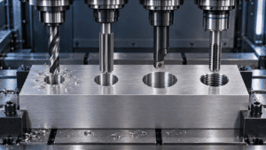
Use standard drill diameters whenever possible. A drilled hole is economical, but a close-tolerance diameter may require reaming, boring, interpolation, honing or grinding. Specify the functional tolerance and let the process follow from it.
Keep ordinary hole depth near four diameters when possible. Deeper holes may need peck drilling, through-tool coolant, gun drilling or two-sided access. For blind holes, account for the drill-point cone and chip space.
Provide edge distance and tool access. Closely spaced holes, intersecting passages and holes entering curved or angled surfaces may wander or create burrs that are difficult to remove.
Specify Threads Completely
Use common metric or unified thread standards and avoid unnecessary thread depth. Full thread engagement of roughly 1 to 1.5 times nominal diameter is sufficient for many applications; the correct value depends on the fastener and material. Excessive depth adds no useful strength after the engaged length is already adequate and increases the risk of tap breakage and chip packing.
For blind threads, provide extra drilled depth. State designation, class, thread depth, entry side, inserts and whether coating or masking applies.
Avoid or Standardize Undercuts
Undercuts cannot be reached by a standard end mill from a direct approach. They may require T-slot, dovetail, keyseat, lollipop or custom cutters. When an undercut is necessary, use standard widths and provide enough clearance for the cutter body and shank.
As a starting point, many standard undercut tools support a depth near twice their cutting width, while internal clearance may need to be several times the feature depth. Confirm actual tooling. If the feature exists only to clear a mating corner, redesigning the mating part or adding a simple relief may be less expensive.
Reduce Setups and Reorientations
Every setup adds loading, probing, datum transfer, programming, inspection and error between orientations. Group related critical features in one clamping when possible.
Design obvious, stable workholding surfaces. Provide enough stock or geometry for clamps, jaws or fixtures without damaging functional areas. Parts with no parallel faces, very thin edges or critical surfaces on every side may need soft jaws, vacuum fixtures, adhesives, sacrificial tabs or custom fixtures. For more detail, see our guide to CNC fixture design for repeatable precision machined parts.
Multi-axis or mill-turn equipment can reduce setups, but a simpler machine with a good fixture may be cheaper at volume. Ask the supplier to compare routes during quotation.
Use a Functional Datum and Tolerance Strategy
Select datums that represent how the part locates in the assembly and can also be established during machining and inspection. Avoid dimension chains that accumulate variation. Use baseline or ordinate dimensions from stable references, and use GD&T when it communicates position, profile, orientation or runout more directly.
Apply tight tolerances only to critical features. General tolerances can control the rest. Complete an assembly tolerance stack-up before reducing a part tolerance, because the root problem may be spread across several components. For deeper tolerance planning, review our CNC machining tolerances guide.
Surface roughness does not replace flatness or size control. Call out each requirement only where it affects function.
Plan Secondary Operations Early
Anodizing, plating, heat treatment, passivation, electropolishing, bead blasting, powder coating and polishing can alter dimensions, edges, surface texture and distortion. State whether dimensions apply before or after the operation. Add machining or grinding allowance where required.
Identify masked bores, threads, contacts and sealing surfaces. For hardened parts, define which features are roughed before heat treatment and finished afterward.
Design for Deburring, Cleaning and Marking
Define edge condition: break sharp edges, apply a specific chamfer or preserve a controlled sharp edge. Cross-holes and intersecting internal passages can trap burrs that are difficult to see or remove. Add access for brushes, abrasive flow, flushing or inspection when cleanliness is critical.
Prefer recessed text, simple fonts and adequate stroke width. Use laser or ink marking when machined text adds unnecessary cycle time.
Make the Part Inspectable
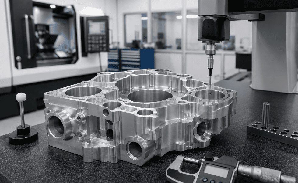
A requirement that cannot be measured reliably is not production-ready. Ensure datums are accessible to fixtures and inspection equipment. Deep internal profiles, hidden undercuts and flexible walls may require special gages, scanning, sectioning or functional tests.
Define required first-article, CMM, material, coating, capability or sampling records. Agree on temperature, plastic conditioning, measurement method and acceptance rules.
Common CNC DFM Mistakes and Better Alternatives
Common mistake | Why it increases risk | Better DFM choice |
Sharp internal corners | Require very small cutters or EDM, increasing time and cost. | Use larger radii, corner reliefs or dog-bone clearance. |
Overly tight tolerances everywhere | Raises machining, inspection and scrap cost without improving function. | Reserve tight tolerances for critical interfaces and use general tolerances elsewhere. |
Deep narrow pockets | Cause tool deflection, chatter and poor surface finish. | Open the geometry, increase corner radius or split the design. |
Thin unsupported walls | Can distort during cutting, clamping or stress release. | Add ribs, shorten unsupported spans or leave temporary support stock. |
Unclear datums | Makes machining and inspection references inconsistent. | Define functional datums that match assembly and inspection needs. |
Ignoring coating thickness | Can make bores, threads and fits nonconforming after finishing. | State whether dimensions apply before or after finishing and define masking. |
Release a Complete, Nonconflicting RFQ Package
Send a native or neutral 3D model, commonly STEP, plus a controlled 2D drawing for tolerances, GD&T, threads, finishes, notes and inspection requirements. Include material specification, quantity, revision, desired delivery and any approved substitutes.
State which document governs if the model and drawing conflict. Remove duplicate dimensions and obsolete notes. For model-based definition, confirm the supplier can read the semantic annotations and named standard.
Easiahome can review your CAD model and 2D drawing before quotation to identify cost drivers, tolerance risks, workholding challenges, inspection requirements and lead-time issues. If your project needs precision machined parts, our CNC machining services team can help turn a functional design into a practical manufacturing plan.
Final CNC DFM Checklist
- Critical functions and mating interfaces are identified.
- Material, temper, condition, stock form and grain direction are specified.
- Standard tools, holes, threads, radii and undercuts are used where possible.
- Pockets, bores, walls, floors and tool reach have acceptable aspect ratios.
- The tool holder and workholding fixture have physical access.
- Critical related features can be machined from a common setup or datum.
- Tolerances and GD&T protect function without unnecessary precision.
- Coating, heat treatment, masking and final dimensional state are defined.
- Burr removal, cleaning, marking and edge conditions are specified.
- Datums and critical features can be inspected with an agreed method.
- The 3D model, drawing, revision, purchase order and inspection plan agree.
- Prototype findings will be incorporated before volume production.
FAQ
Q: What is DFM in CNC machining?
A: DFM, or design for manufacturability, means adjusting a part design so it can be machined reliably at the required cost, tolerance, quality and lead time. For CNC machining, DFM covers tool access, material, workholding, setups, tolerances, finishing and inspection.
Q: How can DFM reduce CNC machining cost?
A: DFM reduces cost by using standard tools, avoiding unnecessary tight tolerances, limiting difficult features, reducing setups, improving workholding and preventing scrap or rework.
Q: What wall thickness is best for CNC machined parts?
A: There is no universal minimum. As a starting point, many designs use about 0.8 mm or more for metal walls and about 1.5 mm or more for plastic walls, but wall height, material, unsupported length and tolerance are just as important.
Q: How do tolerances affect CNC machining price?
A: Tighter tolerances usually require slower machining, more stable workholding, additional inspection and sometimes secondary finishing. Apply tight tolerances only to features that control function, fit or assembly.
Q: What files should I send for CNC DFM review?
A: Send a 3D CAD model, 2D drawing, material specification, surface finish, quantity, target lead time, tolerance notes, inspection requirements and any assembly or cosmetic restrictions.
Conclusion
Effective CNC DFM considers the complete manufacturing route, not only minimum wall thickness and cutter radius. The strongest designs connect functional requirements to material, stock, tools, access, workholding, setups, tolerance, finishing and inspection.
Use recommended geometry where possible, distinguish feasible from repeatable at production scale, and involve the machine shop before the drawing is frozen. A short DFM review can remove hours of machining, prevent inspection disputes, improve yield and shorten the path from prototype to dependable production.