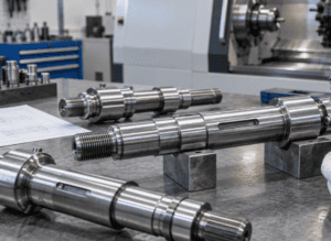
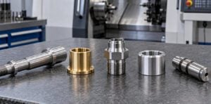
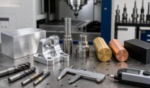
Shaft machining is a critical manufacturing process for components that transmit power, support rotating assemblies or maintain accurate alignment. From compact motor shafts to long transmission shafts, these parts often combine several demanding requirements: tight diameter tolerances, controlled runout, durable bearing seats and precisely positioned keyways, splines or threads.
A shaft that looks simple in a CAD model can become expensive if its material, tolerances or surface finish are not matched to its function. This guide explains the main CNC shaft machining processes, common materials, dimensional requirements and practical design decisions that help manufacturers produce reliable parts at a reasonable cost.
What Is Shaft Machining?
Shaft machining produces cylindrical components through CNC turning, milling, drilling, grinding and finishing. Most shafts begin as round bar, tube or forgings before diameters, shoulders, grooves, threads and torque-transmitting features are cut.
Common shaft types include straight shafts, stepped shafts, hollow shafts, eccentric shafts, splined shafts and threaded shafts. They are used in motors, pumps, gearboxes, conveyors, vehicles, robotics, medical equipment and industrial machinery.
CNC turning normally creates the primary cylindrical geometry. Milling adds keyways, flats, slots and cross holes. Grinding may then refine bearing seats or sealing surfaces that require closer tolerances and smoother finishes than turning alone can provide.
Common Shaft Machining Processes
CNC Turning
CNC turning is the main process for producing shaft diameters, shoulders, tapers, grooves and end faces. The rotating workpiece is cut by a stationary tool, making the process efficient for concentric features. Live-tool lathes can also drill off-center holes or mill simple flats without transferring the part to another machine.
Long, slender shafts often need a tailstock or steady rest to reduce deflection and chatter.
CNC Milling
Milling produces keyways, wrench flats, slots and complex end geometry. A turn-mill center can complete these operations in one setup, improving alignment and reducing handling.
Grinding and Finishing
Cylindrical grinding improves diameter accuracy, roundness and finish after turning or heat treatment. Centerless grinding is efficient for higher volumes, while polishing can refine sealing and sliding surfaces.
Secondary operations can include drilling, tapping, broaching, knurling, straightening, heat treatment, coating and inspection.
Shaft Machining Tolerances and GD&T Requirements
Shaft tolerances should be based on function, especially at bearing seats, seals and coupling interfaces. Tight tolerances on every diameter increase machining, inspection and scrap costs without improving performance.
Diameter tolerances control the type of fit between a shaft and a mating component. A clearance fit allows assembly and movement. A transition fit provides accurate location with limited clearance, while an interference fit creates a secure connection through press fitting or thermal assembly. Standard fit systems should be used whenever possible.
Important geometric controls include:
– Straightness, which limits bending along the shaft axis.
– Circularity, which controls each circular cross-section.
– Cylindricity, which controls the full cylindrical surface.
– Concentricity or position**, which relates separate features to a common axis.
– Total runout, which controls the combined variation of a rotating surface relative to a datum axis.
Runout is especially important for bearing seats, seals and high-speed rotation. Clearly defined datums guide setup and inspection. State critical tolerances on a 2D drawing rather than only in the 3D model
Keyways, Splines and Other Shaft Features
Keyways transmit torque between a shaft and a gear, pulley or coupling. Parallel keyways are common and economical. Woodruff keyways use a semicircular pocket that helps locate the key and can suit tapered or smaller shafts.
Keyway width, depth and position influence fit and torque transfer. An unnecessarily deep keyway reduces the shaft’s effective cross-section and can create a fatigue concentration. Designers should use standard key dimensions and include suitable corner radii whenever the mating assembly allows them.
Splines distribute load across multiple teeth and suit higher torque or axial movement. Involute splines improve load distribution and alignment, but their tooling and inspection usually cost more than conventional keyways.
Position threads, retaining-ring grooves and cross holes away from highly stressed transitions where possible. Specify deburring because burrs near a bearing seat or oil hole can disrupt assembly.
Surface Finish Requirements for Machined Shafts
Surface finish affects friction, sealing, wear and fatigue performance. A general turned surface may be acceptable for non-contact diameters, while bearing and seal locations often require fine turning or grinding.
Surface roughness is commonly specified as Ra. Requiring a very low value across the entire shaft adds cost, so assign it only where function requires it.
Bearing seats need consistent geometry and a finish compatible with the selected fit. Dynamic seal surfaces require controlled roughness and machining direction because deep or spiral tool marks can create leakage paths. Sliding surfaces may need grinding, polishing or coating to reduce friction and wear.
Design drawings should distinguish functional surfaces from cosmetic ones. A statement such as “Ra 0.8 µm on bearing seats; Ra 3.2 µm elsewhere” is usually more economical than requiring the entire part to meet the finer value.
Heat Treatment and Surface Treatment
Heat treatment can improve shaft strength, hardness and wear resistance. Common options include through hardening, quench and tempering, carburizing, nitriding and induction hardening. Induction hardening is useful when selected surfaces require wear resistance while the shaft core must remain tough.
Heat treatment can distort slender components. Precision shafts are often rough machined, heat treated with grinding allowance, then finish ground. Specify hardness, treatment depth and whether dimensions apply before or after treatment.
Surface treatments include black oxide, electroless nickel plating, hard chrome plating and passivation. Aluminum shafts may be anodized, while stainless steel parts may be passivated to improve corrosion performance. Coating thickness must be considered on close-fitting diameters.
Design Tips to Reduce Shaft Machining Cost
Start with standard bar close to the largest finished diameter. Use standard threads, keyways, grooves and radii so the manufacturer can use available tooling.
Keep tolerances practical. Reserve tight diameter, runout and surface-finish requirements for bearing, seal and coupling locations. Avoid deep narrow grooves, sharp internal corners and extreme diameter changes. Add fillets at shoulders to reduce stress concentration, while confirming that mating components provide adequate clearance.
For long shafts, consider whether the design can use a larger diameter, shorter unsupported length or separate assembled components. Where several features must remain concentric, identify them clearly so they can be machined in the same setup.
Provide prototype and production quantities so the supplier can select a suitable process and distribute setup and inspection costs accurately.
What to Include in a Shaft Machining RFQ
A complete request for quotation helps prevent delays and overly conservative pricing. Include:
– A STEP or other 3D CAD file.
– A 2D technical drawing with dimensions, datums and GD&T.
– Material grade and supply or heat-treatment condition.
– Critical diameters, fits, runout and straightness requirements.
– Keyway, spline, thread and groove specifications.
– Surface roughness and coating requirements.
– Target hardness and case depth where applicable.
– Prototype and production quantities.
– Inspection documents, material certificates and delivery requirements.
Also describe the operating load, speed, temperature and environment when material or finish selection is not final. These details allow the manufacturer to identify manufacturability risks before production.
Frequently Asked Questions
Q: What is the best material for a machined shaft?
A: 1045 steel suits many general-purpose shafts, while 4140 is preferred for higher loads. Stainless steel is appropriate for corrosive environments, and aluminum or titanium may be selected when weight is critical.
Q:What tolerances can CNC shaft machining achieve?
A: Achievable tolerance depends on diameter, length, material and process. Turning can hold many standard fits, while precision grinding is often used for demanding bearing seats, roundness and runout requirements.
Q:How are keyways machined in shafts?
A:Keyways can be produced by CNC milling, slotting, broaching or specialized cutters. The best method depends on keyway type, shaft geometry, tolerance and quantity.
Q:What surface finish is required for a bearing shaft?
A:The correct finish depends on the bearing type, fit and operating conditions. Bearing manufacturers’ recommendations should guide both roughness and dimensional tolerance.
Q:How can the cost of a long shaft be reduced?
A:Use realistic straightness and runout requirements, avoid unnecessarily small diameters, provide support-friendly geometry and limit precision grinding to functional surfaces.
Request a Custom Shaft Machining Quote
Reliable shaft production begins with the right combination of material, geometry, tolerance and finish. A manufacturability review can identify expensive features, weak datum schemes and avoidable inspection requirements before they reach the shop floor.
Send EASIAHOME your CAD model, technical drawing, material requirement, quantity and operating conditions. Our engineering team can review your custom shaft design, recommend a practical manufacturing route and prepare a CNC shaft machining quote for prototypes or production parts.