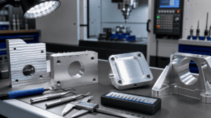
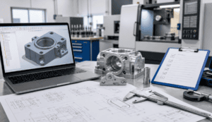
Tolerance is the permitted variation from a nominal dimension or geometric requirement. It is not the same as the machine’s display resolution, and it is not a single number that applies to every feature on a part. A modern machining center may move in very small increments, yet the finished component is still influenced by tool deflection, workholding, thermal growth, material movement, inspection uncertainty, and the number of setups.
The best tolerance strategy therefore starts with function. A bearing seat, sealing face, dowel-hole pattern, or rotating diameter may need close control. A clearance pocket or cosmetic outside profile usually does not. Specifying the same tight tolerance everywhere increases machining and inspection cost without necessarily improving the assembly.
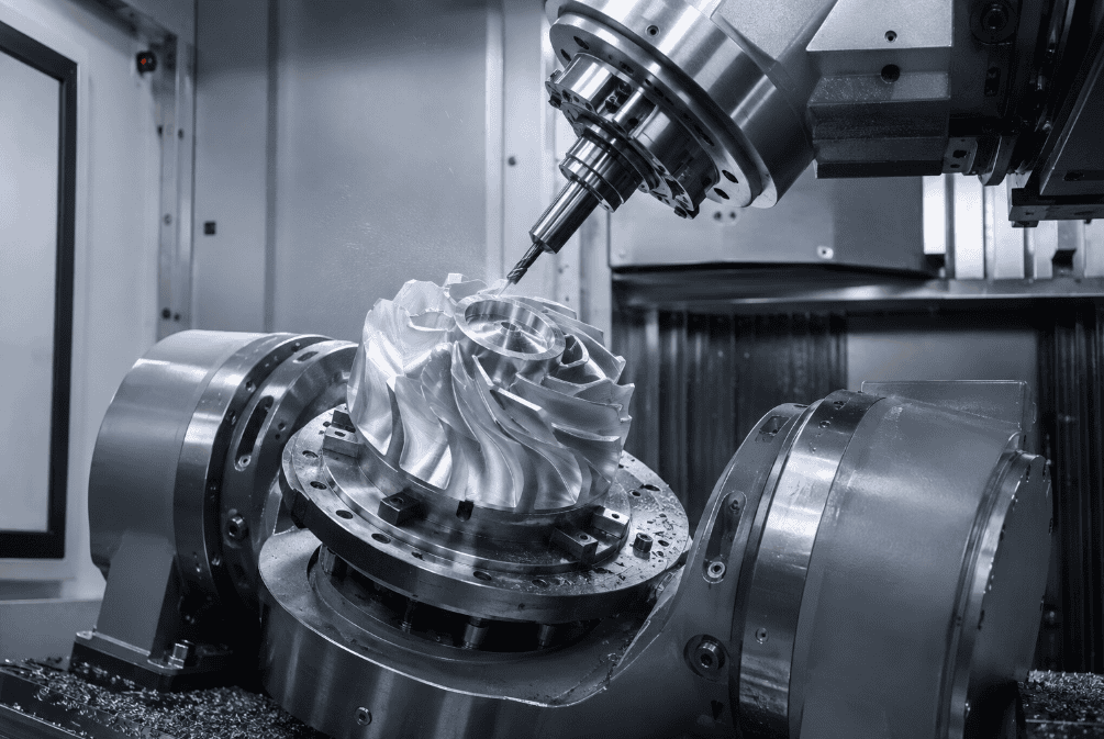
What Does a CNC Tolerance Control?
A complete part specification normally uses several types of control:
- Size tolerancelimits length, width, diameter, thickness, or the distance between opposite surfaces.
- Geometric tolerancecontrols form, orientation, location, profile, or runout. Examples include flatness, perpendicularity, position, and total runout.
- Surface texturedescribes microscopic roughness, commonly with an Ra value. Surface roughness is important, but it does not replace dimensional or geometric tolerances.
- Edge requirementsdefine whether edges are sharp, chamfered, radiused, or simply deburred.
These controls solve different problems. A hole can meet its diameter tolerance but still be in the wrong location. A shaft can meet local diameter measurements but have unacceptable runout. A flat sealing face can have the correct thickness while failing flatness. Good drawings state the requirement that actually protects function.
ISO 2768: What It Covers—and What Has Changed
ISO 2768-1 establishes general tolerances for linear and angular dimensions that do not have individual tolerances. It uses four classes: fine (f), medium (m), coarse (c), and very coarse (v). The permitted variation increases with nominal size, so “ISO 2768-m” does not mean one constant plus-or-minus value across the entire drawing.
As a simplified reference, ISO 2768-1 fine and medium classes allow smaller deviations for short dimensions and progressively larger deviations for long dimensions. For example, publicly available manufacturing summaries show ±0.05 mm for fine-class linear dimensions from 0.5 to 6 mm, while medium class is commonly ±0.10 mm over the same range. Between 30 and 120 mm, the published summaries increase to approximately ±0.15 mm for fine and ±0.30 mm for medium. Always consult the licensed standard and the edition named in the contract before releasing a production drawing.
There is also a status detail that many machining guides miss. ISO lists ISO 2768-2:1989, formerly used for general geometrical tolerances, as withdrawn and identifies ISO 22081:2021 as its replacement. ISO 1101 defines the symbol language and interpretation rules for explicit geometrical tolerancing. In August 2026, ISO also showed the second edition of ISO 2768 in the publication process, while ISO 2768-1:1989 remained the published edition. For controlled industries, write the complete standard designation and edition in the title block, and confirm the supplier is using the same interpretation.
When to Use General Tolerances
General tolerances are useful for noncritical dimensions because they keep drawings readable. A title-block note can cover ordinary lengths, diameters, radii, chamfers, and angles, while critical features receive individual limits.
Do not rely on a general note for a press fit, bearing seat, seal diameter, precision hole pattern, locating datum, controlled wall thickness, or a dimension affected by coating. These features should be toleranced directly and connected to a clear datum system when location or orientation matters.
Also avoid mixing systems casually. ISO GPS and ASME Y14.5 are both mature specification systems, but their defaults and terminology are not interchangeable in every situation. State which system governs the drawing.
GD&T for CNC Machining
Geometric dimensioning and tolerancing communicates how a feature may vary while the part still functions. A feature control frame can control straightness, flatness, circularity, cylindricity, profile, parallelism, perpendicularity, angularity, position, circular runout, or total runout.
The main advantage is functional clarity. Suppose four clearance holes must align with a mating assembly. Applying very tight plus-or-minus coordinate dimensions can create a square tolerance zone and may reject parts that would assemble correctly. A position tolerance can define a cylindrical zone around the true location. When material-condition modifiers are appropriate, the design may also gain bonus tolerance as the actual hole moves away from maximum material condition.
GD&T is not automatically cheaper. It saves cost only when the datum reference frame matches assembly function, the tolerance is realistically sized, and the supplier can inspect it. A complicated callout with no inspection plan creates quoting delays and disagreement. Use the simplest control that fully defines function.
Realistic CNC Machining Tolerance Ranges
The following ranges are practical estimating bands for reasonably sized, stable parts made with capable equipment and controlled processes. They are not promises. Actual capability must be reviewed against the drawing, feature size, aspect ratio, material, quantity, machine, fixturing, and measurement method.
Feature or process | Practical estimating range | Important conditions |
General milled dimensions | ±0.05 to ±0.13 mm | Short-to-medium dimensions, stable metal, accessible features |
General turned diameters | ±0.02 to ±0.05 mm | Rigid workpiece, moderate length-to-diameter ratio |
Reamed or precision-bored holes | ±0.01 to ±0.025 mm | Suitable diameter, controlled tool wear, in-process inspection |
Selected high-precision features | ±0.005 to ±0.01 mm | Small stable features; added finishing, inspection, and process control |
Machined engineering plastics | ±0.10 to ±0.25 mm | Strongly affected by polymer, moisture, temperature, and geometry |
Large or thin-walled parts | Drawing review required | Thermal growth, residual stress, workholding, and datum transfer dominate |
Tolerances below about ±0.01 mm are not simply a matter of entering a smaller number in CAM software. The part may need grinding, honing, lapping, jig boring, climate-controlled inspection, matched process stages, or custom fixturing. Extremely close limits on every dimension can make the part uneconomical or impossible to verify consistently.
What Determines Achievable Accuracy?
Material behavior. Aluminum machines predictably but can release residual stress after heavy stock removal. Hardened steel increases cutting forces and tool wear. Thin stainless steel may distort. Nylon absorbs moisture, while PTFE and other soft plastics can deform under cutting and measurement forces.
Feature geometry. Deep pockets, long bores, slender shafts, thin floors, and tall walls reduce rigidity. A tolerance achievable on a short external diameter may be unrealistic on a deep internal feature.
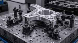
Tool access and setup count. Features produced in one setup preserve their relationship more easily than features transferred between fixtures. Every reorientation introduces datum-transfer and clamping error. Five-axis machining can reduce setups, but it does not eliminate thermal, tool, or inspection effects.
Temperature. Metals expand with temperature. A long aluminum component measured warm beside a machine may not match the same measurement after stabilization in an inspection room. Tight specifications should define the reference temperature and allow the part to normalize before final inspection.
Secondary processing. Anodizing, plating, heat treatment, passivation, polishing, and blasting can change dimensions or edges. State whether the limit applies before or after finishing. For a coated bore or threaded feature, define masking and final inspection requirements.
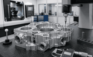
Measurement capability. A tolerance is incomplete without a credible verification method. Calipers may be adequate for general dimensions; close bores may need air gaging or bore gages; complex position or profile controls may require a CMM or scanning system. Measurement uncertainty should be small enough to support the acceptance decision.
How Tight Tolerances Increase Cost
Tighter limits often require slower cuts, more finishing passes, frequent tool compensation, lower material-removal rates, stabilized workpieces, additional setups, special fixtures, and more inspection. They can also reduce yield because a small process shift creates nonconforming parts.
The lowest-cost drawing is not the drawing with the loosest possible numbers. It is the drawing that tightly controls only the features that drive fit, sealing, motion, alignment, fatigue life, or safety. Use tolerance stack-up analysis to allocate variation across the assembly instead of placing the entire burden on one component.
Drawing Checklist for Reliable CNC Tolerances
Before requesting a quote, confirm the following:
- Identify the governing dimensioning standard and edition.
- Apply a sensible general tolerance to noncritical dimensions.
- Tolerance critical fits, hole patterns, sealing faces, and datums individually.
- Create a datum reference frame that reflects how the part is assembled or inspected.
- Avoid duplicate, chained, or conflicting dimensions.
- State whether dimensions apply before or after coating and heat treatment.
- Define surface roughness only where it affects function.
- Specify threads completely, including standard, class, depth, and insert requirements.
- Identify the required inspection method, sampling plan, and report format.
- Review unusual tolerances with the machine shop before production.
Conclusion
Reliable CNC tolerancing is a balance between function, manufacturability, and verification. ISO 2768 can simplify noncritical dimensions, while GD&T can communicate functional relationships more clearly than blanket plus-or-minus limits. Neither system replaces engineering judgment or supplier review.
Start with assembly function, select meaningful datums, separate size from geometry and surface texture, and account for material, setup, finishing, and measurement. That approach produces parts that fit and perform without paying for precision that the design does not need.